Now I have been lazy with posting on this and all... this being the blogging and stuff but...
IT FLIES.
Using square lexan from McMaster worked out well, the stuff is more flexible then carbon fiber but much less prone to cracking or splitting and relatively cheap. Getting the KK2 chip tuned in was a bit of a hassle however once I learned to turn on height damping. This effectively keeps the quad from dropping when you do any kind of maneuvers. Now technically you are suppose to do this by yourself, add a bit of throttle when you tilt forwards but used to driving FRC robots at 100% power this was a learning curve... So cheating and making the on board gyros/accelerometers do all the work with some finely tuned PIDs makes flying this thing almost easy.
However I did in the process of tuning and learning to fly go though all my props *sigh...
New ones are on the way as well as more flight training.
Well there it was this morning, looking pretty good. There was one more plate to be bolted on over the KK2 for the battery to be velcroed to. Everything seemed pretty solid and all the electronics powered up and tested fine. The KK2 was an pleasure to setup and do the initial ESC and sensor calibrations. So I strapped on a battery and went outside to do some flight testing on it; now my RC flying skills or lack thereof are a bit rusty. And well some of my design choices could have been better so what the quad looked like after the flight...
Yeah... and specifically:
Bad material choice bites me in the ass
The carbon fiber tubes split nicely along the seams after a few hard landings and eventually came apart. Well lesson learned cheap carbon fiber from China has some issues. Tube was a 10mm square with an 8mm circle running through it so the walls were only 1mm thick on each side; and all the fibers running in one direction... With the rails completely useless I disassembled the quad and cleaned off the dirt from it and planned out revision 2. Now the few tries I was able to get the thing in the air successfully and it seemed to work pretty well; I had issues with it drifting around but I think that was my lack of control over the craft and the gusty wind.
So after tearing it apart revision two started:
Solidworks <3
So the carbon fiber has been replaced with .5 alum box stock 1/32 wall thickness, roughly the same weight but stiffer and 6061 doesn't suffer cracking issues. I do however need to check if I have any .5 box, if not other solutions will be sought but probably not going to touch carbon fiber. Thinking about it, using clamps with round stock carbon fiber instead of drilling though it would have probably worked out well. But I digress, the booms are also now .5 inch shorter and the landing legs moved closer to the center. In the last iteration they were all the way to the edge which acted as a lever amplifying forces from hard landings. Also the landing legs will be made longer so the blades are father from the ground, broke 2 already on the last bad landing...
So as soon as I can go back to the shop more laser-ing and CNC-ing the above should happen. "These kinds of parts are really simple and quick to fabricate especially with CNC gear. So hopfully the rebuild should be done in a week or two at the most.
It's been awhile since I have posted anything on this. But I have been working! (some might disagree..) So this quadcopter thing...
The classic Quadcopter. This is something I have been wanting to do for awhile and now has finally materialized. The basics goals of this was: 1. Cheap but not cheap2. Custom frame aka not a kit build. 3. Can carry a small HD camera [goPro]
The frame is laser cut from a 1/8 delrin sheet that makes up the body and the motor mounts. The Struts are 10mm carbon fiber box from Hobbyking while the landing gear is laser cut wood; with the intent to be swapped for bigger ones when a camera is attached. The main bulk the electronics is sourced from Hobby King, and the main control board is the new KK2. And because everyone loves photos:
I also picked up an Spektrum 6 Channel Radio and receiver for control and also future projects. One more order from McMaster should provide the raw materials and fastening hardware.
Time to get organized, to much to do to little time to do it.
FRC 2012: Out with the old in with the new, attempting more fixes/upgrades on the old base is becoming even more so pointless so a entire new West Coast Drive base is in the works as well as a new bridge manipulator. Shooter/Tower will remain with some tweaks to the feed and a bunch of updates to code will be added. This will be happening for sure, parts are already in the mail.
GoKart: Since my last post about this most of the CAD work is done and the BOM has been created. However totaling almost $900 this one will probably be on hold till a later time, optimistically next summer. But the research done for this will be useful for future things. A more updated CAD post might happen.
Swerve drive: this is something that could be for FIRST however for actual competition use is very unlikely. More of just something to mess with for fun, CAD is somewhat done on this and the projected cost should be $200-$300 mainly due to the absolute encoders required to control the modules.
Quadcopter: this is a new one, so far just research have been done on this. Seeing that almost every hobbyist has built one, should be a fairly simple project. Hobbyking controller/EMCs/Motors, some carbon fiber and a few 3d printed pieces should be most of it. However a good radio is $200 [Dx7] but well worth it for future projects/builds.
So our school as an math open house event, which is the same thing as a science far but instead of science it is all math projects with Calculus and Mathematica programming. Being the guy with a new CNC laser to play with, a robot with an acrylic base was the logical choice.
Simple and effective, acrylic laser cut base with 2 L brackets for servo motors, lathed Delrin sliders and an Arduino as the brain. Now to get my Mathematica points [which were required] the brute of the programming that runs this was done in Mathematica and the than a serial comm link ferries the data to the Arduino and then servos.
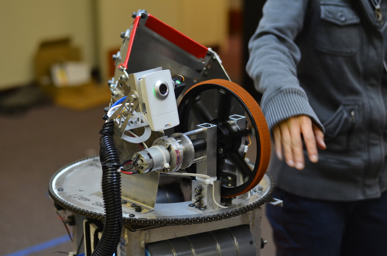
So most important bit of the game this year, getting balls to go into hoops. Simple Right? Fuck no.
The most common and "easiest" shooting mechanism is a one or two wheel baseball pitching machine alike. Either using two wheels or a single wheel with some sort of hood, then just a roller to get the ball close enough for the shooter well to grab onto it and fire. Again sounds easy right, and again the answer would be no.
So what was wrong with version 1? Shooter gearbox was cantilevered out way to far adding to much vibration to the system, there wasn't enough reduction for torque, PID never got implanted fully, feeding was a guessing game, hood wasn't optimal, not even close to enough testing, and the whole assembly was a massive pain the butt to work on. In the end the system did allow use to score a few 2 pointers per match at best, but I wanted 1717 like 3 pointers...
First thing that was done was while the sheet metal hood while a cool concept it was scrapped and replaced with a 1114 two angle lexan hood. This allowed for key and fender shooting and was lighter. Very simple and very effective. It was also machined out more carefully and less last minute, which turned out to be pretty nice.
Now the angles probably need a bit of tuning for the most optimal shooting performance but that rickty gearbox needed to go before any testing was done. After having to deal with how annoying the first revision was to work on revision two was to have a cantilevered wheel, and the whole assembly was designed so that anything could be removed quickly and without frustration; motor can be replaced in 2 minutes flat. It was designed, as everything should be, in Solidworks and changed a million times before ever reaching a drawing file. The design was pretty simple, using the L-brackets and the bolt holes from one of the stand offs on the old shooter; a new gearbox made up of two plates, 5:1 single stage gear reduction and a key slotted shaft was born.
Also at this time we got our sponsorship with Makerplace going and with access to full size and precise bridgeports/lathes, machining consisted of 4 parts. 2 Plates, 1 Box, and 1 shaft, this ended up taking 11 hours..., working to be faster at doing this is something on my to do list...
Well the easy part was done, a solid gearbox and shooter assembly with a good amount of reduction and a top end measured speed of 4100RPMs, now to give it a close loop control system. There is a EP4 4x optical encoder mounted on the back of the gearbox, using a basic PID loop designed with velocity in mind [thanks 399!] and swaging some constants values eventually it basically worked. I will spare the technically details of this for another day because even for me it wasn't very fun.
With all of the above, we can score a whole lot better:
But that doesn't mean it is done, everything keeps iterating. The shooter PID needs a setfoward constant or something to help it spin up faster, with 330watts of power behind it it shouldn't take 4secs to spin back up. And the biggest issue left is the feeding. The belts just power the ball into the shooter, the issue is depending on where the ball is sometimes the balls go into the shooter faster then the last one. This of course results in inconstancies [seen in the video], and needs some kind of mechanical ball loading system.
One fateful day while roaming the vast Internets I came across this: youtube link
Of course I wanted to build one after the first 10 secs of the video... and then a few weeks later: Instructables
So after some pondering, and misguided thinking [always fun] it turns out this is something I could do, provided I get the funds. Makerplace has all the machining I would need for all the parts, the CAD model I can re-create and tweak a bit to fit something more to my tastes and tooling. And anything I didn't know/couldn't figure out can be redeemed by a few hours online, seeing there is quite a few people into this.
Personally a Solidworks user, a few hours in CAD and:
For anyone that has never used 80/20 it is cool stuff, being able to bolt anything to it without drilling holes is a bit of a god send. Of course the downside it is heavier then box and is a bit more expensive but for a project this small well worth the convenience. The frame is held together with 1/4 plates on the corners that double as wheel mounts. The main machining work that needs to be done is just 2d work on 1/4 and 3/16 inch plates. However unlike the DPRCibikart I have redesign the wheel and motor mounts with blocks and L brackets because I have access to a full sized mill. The steering "wheel" is something I might play with around more. And I am considering making the entire frame a bit longer but need to figure out the ergonomics of that first.
Electrical wise a pair of TURNIGY SK motors and controllers makes the round thingys in the back spin really fast. The exactly motor and controller combo is still up for debate, personally I want something with more power then the DPRC, but we will see how far I can stretch a budget and how feasible it would be for me to wire/program a Hall effect sensor. Using FRC CIM motors, gearboxes and controllers was considered for a bit but figures seem to show that buying all of that vs buying what I need for a brushless setup would require the same budget and the brushless is more effiecent and lighter. That leaves the problems of batteries which could be a whole post on it's own so lets not go there. Just suffice to say there will be 15-20AH at 24vs providing the power.
I also need to do some math to figure out what kinda reduction and wheels to put on, as this is not a blatant copy of the DPRC [okay maybe it is...], going to 6inch wheels with more reduction sounds like a good idea, or maybe not need to figure that out. Since 6 inch wheels allows for more reduction without loosing top end speed which should result in more torque. Personally my first goal with this is to make something that will give me a heart attack every time I or anyone comes near the pedal; quite a immature goal I know but I can't help it. I like speedy things.
The only problem in all of this is money, it an't cheap. About $800+ it is quite the under taking in the world of things I have done. With FRC being funded mostly by sponsors this is going to require some piggy bank cracking.
With build and competition season over I have finally been able to catch my breath and get some thinking done. The season was mine and the team's second year in FRC and holy crap was it a crazy. The game reverted back to balls which opened the gates on past knowledge; first has done an number of ball picking and shooting [2006,2009] games before and many of the robots, including ours, had designs familiar to many.
Currently in off season mode, we are redesigning/rebuilding anything that could benefit improvement, iteration for the win. The robot that was used for the regionals... well lets just say a lot has changed since then. Photo from the end of build for reference:
The first iteration was the result of the 6 weeks of build season, and for me at least left a lot to be desired. Now because we are poor [Engineers cannot write] we were only able to attend one regional, so off season started right after SDR. After a quick assessment the rebuild started. And with the help of the slice of heaven known as makerplace new parts began to take over.
Following post and rants should detail the revamp...